


"You stand to be our prime concern & PSI stands by its commitments of
Excellence in Engineering"
STANDARDS
ISO CertificationBSI Kitemark CertificationsTUV CertificationsDesign ConsiderationMaterials And FinishesFloor Cable Management Systems
PROJECT
HIGHLIGHTS
Dubai Metro Rail Project
Doha Metro Rail Project
Riyadh Metro Rail Project
King Abdul Aziz Airport Jeddah
Shuweihat Power Plant Abu Dhabi
Cable Tray & Ladder System
Power Solution Industries offers a comprehensive range of cable tray and ladder products conforming to BS EN 61537 and NEMA VE1.
To design a safe and economical system, it is necessary to consider all the loads applied to the system and establish the criteria by
which it will be judged.
Loads Applied to the System
The weight of cables to be fixed on the system will provide the basic loading data. However, it is always advisable to consider that future system requirements can be expected and allow 20% for additions at a later date. The following should also be considered:
1. The capacity charts provided in this catalogue assume that loading is uniform, both along length and across width. If a point load is applied to the tray / ladder it will potentially have a significant effect and this must be quantified.
2. If components are incorporated in an exterior installation there may be other loading factors to consider, such as wind, ice and snow.
Safe Loading and Deflections
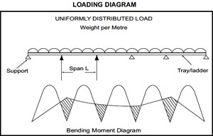
Cable tray & ladder acts as a structural load carrying beam when installed horizontally. The loads imposed and the type and location of supports will create a pattern of bending moment in the structure. Stress will be induced and deflections (vertical displacements) will be observed. A properly specified system will ensure that the stress does not exceed to that which is safe for the materials used in the components.
A suitable installation will require choice of appropriate style of tray / ladder and the location of supports. Increasing the span (horizontal distance between supports) will always reduce safe load carrying capacity and increase deflection.
Location of Supports and Connections
Normally cable tray / ladder is connected together forming a continuous beam over several supports. A typical bending moment diagram shown on the previous page shows the following:
1. Bending moment is much larger in the end spans of the continuous beam than the intermediate spans; which will reduce the load carrying capacity in the end spans. If an installation requires full load carrying capacity along the whole length, than full capacity of the intermediate spans can be used if the end spans are reduced to 0.75L (length of intermediate spans).
2. Bending moment is zero at approximately 0.25L either side of the intermediate supports. These are therefore ideal places to locate connections between component lengths of cable tray/ladder. The installer should avoid placing connections in mid-span positions and at supports. These are positions of maximum bending moment.
3. The diagram shows a typical multi-span beam loading condition. If a loading condition occurs where there is only a single span loading condition it can be taken that the permissible load is reduced to 0.5 that shown for intermediate span in multi-span beams.
4. Only straight length beams are discussed above. When accessories (bends, tees, risers etc.) are involved in an installation they will require extra local support. It is always recommended to use fish plates in conjunction with connectors, particularly when cable trays of greater than 200mm are used. Where earth continuity is an important consideration in a cable tray or ladder system, bonding jumper leads should be used. Cable ladders runs exposed to wide ambient temperature & the variation should incorporate expansion connectors.
Thermal Expansion & Contraction
Installation of cable support and cable management systems must consider thermal expansion and contraction.
The cable ladders & trays should be anchored at the support nearest to its midpoint between the expansion splice plates and secured by expansion guides at all other support locations, refer to Figure 1. The cable ladders trays should be allowed longitudinal movement in both directions from that fixed point.
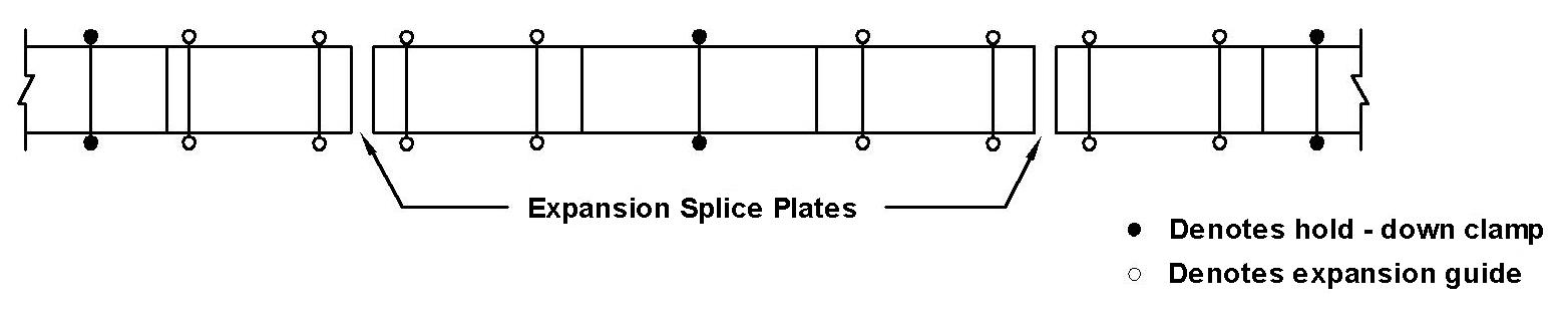
Figure 1
Hold Down and Guide Clamp Locations
Accurate gap setting at the time of installation is necessary for the correct operation of the expansion splice plates. The following procedure should be adopted to determine the correct gap with reference to Figure 2
1. Plot the highest expected temperature on the maximum temperature line
Example Value = 38*C
2. Plot the lowest expected temperature on the minimum temperature line
Example Value = -33*C
3. Draw a line between the maximum and minimum points
4. Plot the temperature at the time of installation to determine the gap setting
Example Value = 9.5mm (10*C)
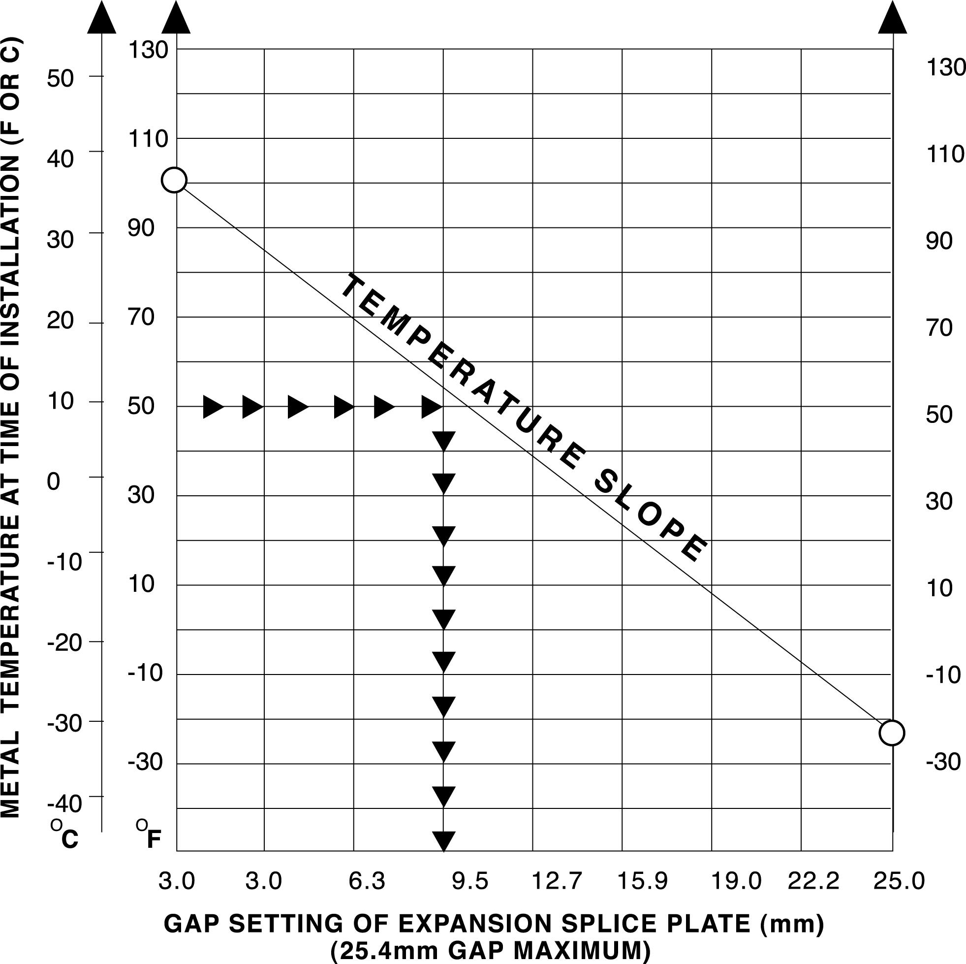
Figure 2
|
Maximum Spacing Between Expansion Joints For 25.4mm Movement |
|||||
|
Temperature Differential |
Steel
|
Aluminium
|
Stainless Steel 304
|
Stainless Steel 316
|
Fiberglass
|
|
℃ |
M |
M |
M |
M |
M |
|
14 |
156 |
79 |
106 |
116 |
203 |
|
28 |
78 |
40 |
53 |
58 |
102 |
|
42 |
52 |
27 |
36 |
39 |
68 |
|
56 |
39 |
20 |
27 |
29 |
51 |
|
70 |
31 |
16 |
21 |
23 |
41 |
|
83 |
26 |
13 |
18 |
19 |
34 |
|
97 |
22 |
11 |
15 |
17 |
29 |
Temperature differential is the difference in temperature between the hottest and coldest days of the year
Expansion joints require bonding for electrical continuity
Supports should be located within 600mm each side of expansion splice plates.